
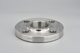
Flange interchangeability depends on a coordinated set of dimensions. Outside diameter alone cannot confirm that two flanges will assemble correctly. Inspectors must consider pressure class, thickness, bolt pattern, bore, hub geometry and facing.
ASME B16.5 covers pressure-temperature ratings, materials, dimensions, tolerances, marking and testing for pipe flanges and flanged fittings within its stated size range. Stainless steel flanges are also commonly ordered to ASTM A182/A182M for material requirements. The two standards address different parts of the product specification.
Confirm flange type, size and class
Begin with the nameplate information: flange type, NPS, pressure class, material grade and standard. Welding neck, slip-on, socket-weld, threaded, lap-joint and blind flanges have different geometries and intended connections.
Pressure class is not simply a pressure value. Allowable pressure depends on material and temperature, so the designer must use the applicable pressure-temperature rating table and piping code.
Flange thickness and hub dimensions
Flange thickness contributes to stiffness and joint behavior. Welding-neck flanges also require checks of hub length and weld-end geometry. Measurements should avoid raised faces where the standard defines thickness from another reference plane.
The bore must match the ordered configuration. For welding-neck flanges, the purchaser should state the intended pipe schedule or bore. A mismatch can create an internal step, poor fit-up or inadequate wall at the weld end.
Bolt circle and bolt-hole inspection
Bolt-hole diameter, number of holes and bolt-circle diameter must match the mating flange. Hole spacing and orientation also affect assembly. Adjacent holes may appear correct while accumulated positional error prevents bolt insertion.
Inspection can use calibrated calipers, templates, height gauges or coordinate measurement depending on size and accuracy. The report should identify the method and sampled quantity.
Facing and gasket-contact surface
Raised-face, flat-face and ring-type-joint flanges require different checks. Facing dimensions, finish and groove geometry influence gasket performance. Surface damage, radial scratches across the sealing area or incorrect machining can contribute to leakage.
The purchase specification should identify facing type and required finish. A roughness value without the facing designation is incomplete.
Flatness, parallelism and alignment
Distortion can occur during forging, heat treatment or machining. Inspectors may check face flatness, parallelism and the relationship between the bore, hub and bolt pattern when required. Fabricated assemblies also need flange rotation and angular alignment control to avoid forcing the joint into position.
Material and documentation checks
For ASTM A182/A182M stainless steel flanges, review the material certificate, grade, heat treatment, chemical composition and mechanical properties required by the order. PMI may be added for alloy verification. Marking and heat-number traceability should remain legible after machining.
What buyers should specify
- Flange type, NPS and pressure class
- ASTM material grade and ASME B16.5 edition
- Pipe schedule or required bore
- Facing type and surface-finish requirement
- Special dimensional tolerances, if any
- PMI, NDE and inspection sampling
- Material certificate and dimensional report requirements
Exact numerical limits should be taken from the project-specified ASME B16.5 edition rather than copied from an uncontrolled web table. A complete inquiry helps the manufacturer select stock, plan machining and prepare an inspection record that matches the buyer’s acceptance criteria.